Gaussian Beams
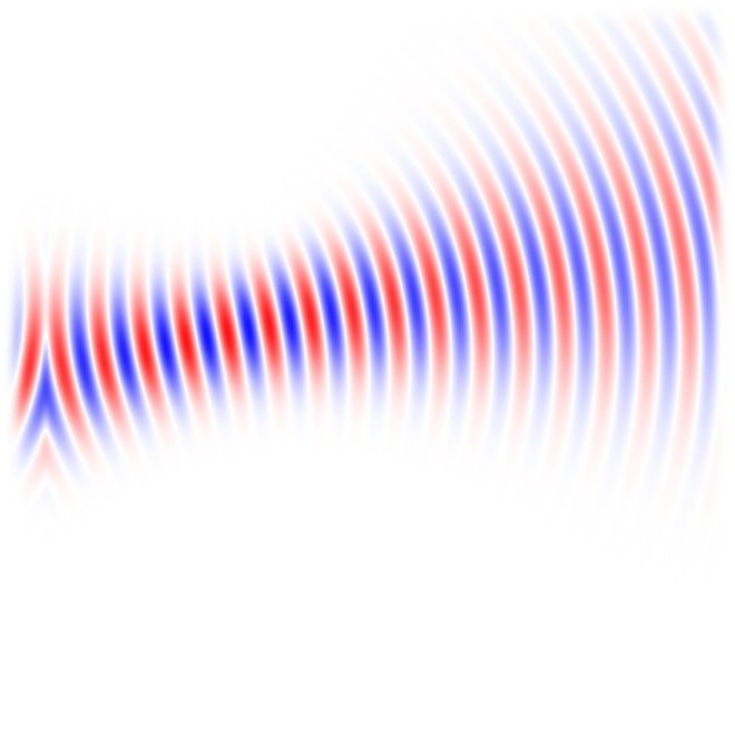
First post! To celebrate, we'll make a Gaussian beam capable of propagating at an arbitrary direction and where we can control the position of the beam waist with respect to the source.

Gaussian beam with displaced waist.
Lets start with the textbook formula for a Gaussian beam with its waist centered at \(z=0\) and propagating along the z-axis:
Above, \(z\) is the position along the z-axis, \(r\) is the distance to the the z-axis, \(z_R\) is the Rayleigh range of the beam and \(k\) its propagation constant (\(k=2\pi/\lambda\)). This equation is usually rewritten in terms of the beam curvature \(R(z)\), spot size \(w(z)\) and Guoy phase shift \(\phi(z)\) as:
with:

Gaussian beam parameters. Courtesy of wikipedia
Despite it being prettier and explicitly mapping the terms inside the exponentials to concrete physical interpretations, the equation above has a problem. A singularity at \(z=0\) is introduced in the \(R(z)\) term. To avoid it we will just implement the first equation. The previous expressions describe a beam propagating along the z-axis (\(\vec{k}=(0,0,k)\)). There are several ways to figure out the correct equation for a beam propagating in any direction. I just did it by inspection. The result is:
where \(z\) is still the distance to the beam waist regardless of the direction of propagation. This last equation can be implemented as:
Note that the function above takes a constant value for k; this means
that when setting the Rayleigh range for the beam we are actually specifying it
only for the frequency at which \(k=\frac{\omega}{c}\). At any other frequency
the beam parameters will be different. The bigger the bandwidth of the source
the more noticeable the effect will be. This is something that can also be
observed when implementing a tilted plane wave using a line source. At each
frequency the angle at which the wave propagates will be different. If for your
simulations it is critical to have well defined beam parameters then the
easiest solution is to add multiple narrow-band sources and only believe the
results at the central frequency of each source. There is a method not
implemented on Meep that allows for broadband plane waves traveling at a fixed
angle.With these definitions, the beam will focus and then diverge if \(z > 0\).
If \(z\ < 0\) then you'll see a beam that is diverging as if the origin was
somewhere inside the source.Now we only have to use the above as the
amp-func and we are done!
Finally, these codes will produce radiation propagating on both sides of the
source. This is not important for most applications and can be worked around if
necessary. Producing a good unidirectional beam is not trivial as explained by
S. G. Johnson on the Meep
mailing
list. On the other hand, getting a more or less unidirectional beam can be done
by introducing another source were we fix the H-component of the field so that
the right-hand rule gives us the desired sense.In the ctl file I decided to
specify the waist size \(w_0\) rather than the Rayleigh range. This keeps me away
from doing stupid things like trying to use a Rayleigh range that would imply a
beam waist much smaller than the wavelength. If you try it you'll find out it
doesn't work at all. Another option would be to specify the divergence angle of
the beam. Remember that if you do so, the less divergence the bigger the beam,
which in turn means you'll need a bigger source to avoid clipping the beam and
introducing diffraction. The different properties of the beam can be related to
each other through the following expressions:
You can find the Meep control file to produce the figures below on GitHub.
 Beam going upwards with waist on source.
 Waist at source.
 Focusing in front of the source with a positive distance to waist.
 Focusing in front of the source.