Distributed Bragg Reflectors
A very common photonic structure is the Distributed Bragg Reflector (DBR). The multilayer DBR has also inspired other structures such a fiber Bragg gratings which in can be integrated into optical fibers.
Distributed Bragg reflectors are frequently used as dielectric mirrors. In their most basic form they consist of a stack of alternating dielectrics with \(\lambda/4\) thickness. In this short post we'll look at a function to create DBRs easily and provide the necessary equations to design them. Then we will look at their frequency response using a scattering experiment and compare the results with transfer matrix method simulations. We'll end by building a DBR microcavity and looking at it's modes.
DBR Design
DBRs only act as mirror with a certain range of frequencies. The design process start by deciding what is going to be the central frequency for the stop band. This parameter determines the thickness of the two types DBR layers. Assuming we want the central wavelength of operation \(\lambda_0\) and that our dielectrics have indices of refraction \(n_1\) and \(n_2\) the thickness of the layers will be:
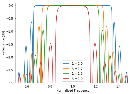
Next we have to decide what band width of operation we need for the device. The bigger the contrast index between \(n_1\) and \(n_2\) the bigger the fractional bandwidth will be. It's value is:
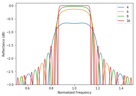
The last step is to decide how reflective you need your mirror to be. The more DBR pairs you use the higher the reflectivity will be. This is given by:


Building the DBR<
The function below returns a list of blocks that will make the DBR. The two let
bindings define the lambda make-pair that returns a list with the two block
that make the unit cell.
Scattering Simulation
In order to see the reflection and transmission response of the DBR we will have to setup a scattering experiment. As explained in the Meep tutorials this will require that we run two simulations, one without the structure and another one with the structure.
For this simulation I will use a plane wave travelling downwards hitting at normal incidence on the structure and will run it until the fields have decayed significantly.

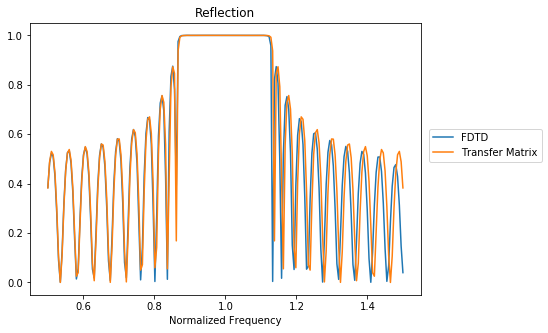
Results of the frequency response of the structure from the FDTD simulation and from the transfer matrix formalism.
As always all the code neccessary to run and analyze the results from the simulation is available at Github.